Inputs are connections that allow the BMS controller to read information from sensors, switches, or other devices.
Outputs are connections that allow the controller to control equipment such as actuators, pumps, fans, and valves.
Think of it this way:

Digital inputs read ON/OFF states (binary signals). Common uses:
Example: A pressure switch connected to a digital input will show:
DI1 = ON when pressure is high (switch closed)DI1 = OFF when pressure is normal (switch open)
Analog inputs read variable values (0–10V, 4–20mA, PT1000, NTC). Common uses:
Example: A PT1000 temperature sensor connected to AI1 might read:
AI1 = 22.5°C (room temperature)
| Input Type | Quantity | Signal Types Supported |
|---|---|---|
| Digital Inputs | 8 | Volt-free contacts, 0–24V |
| Universal Inputs | 8 | 0–10V, PT1000, NTC10K, 4–20mA |
| Input Type | Quantity | Signal Types Supported |
|---|---|---|
| Digital Inputs | 4 | Volt-free contacts, 0–24V |
| Universal Inputs | 6 | 0–10V, PT1000, NTC10K |
Digital outputs provide ON/OFF control (relay or solid-state). Common uses:
Example: A digital output controlling a pump contactor:
DO1 = ON → Pump runsDO1 = OFF → Pump stops
Analog outputs provide variable control signals (0–10V, 4–20mA). Common uses:
Example: An analog output controlling a heating valve:
AO1 = 0V → Valve fully closedAO1 = 5V → Valve 50% openAO1 = 10V → Valve fully open
| Output Type | Quantity | Signal Types |
|---|---|---|
| Digital Outputs (Relays) | 8 | 230VAC / 5A resistive |
| Analog Outputs | 4 | 0–10V |
| Output Type | Quantity | Signal Types |
|---|---|---|
| Digital Outputs (Relays) | 2 | 230VAC / 5A resistive |
| Analog Outputs | 2 | 0–10V |
Let's wire a typical FCU with the following components:

| Problem | Possible Cause | Solution |
|---|---|---|
| Temperature reads 0°C or 255°C | Incorrect sensor type selected | Check sensor configuration (PT1000 vs NTC10K) |
| Digital input always ON | Wiring reversed or short circuit | Verify volt-free contact wiring |
| Valve doesn't respond to AO signal | Incorrect voltage range or broken actuator | Check actuator specification (0–10V vs 2–10V) |
| Relay output doesn't switch | Faulty relay or overload | Check load rating (max 5A resistive) |
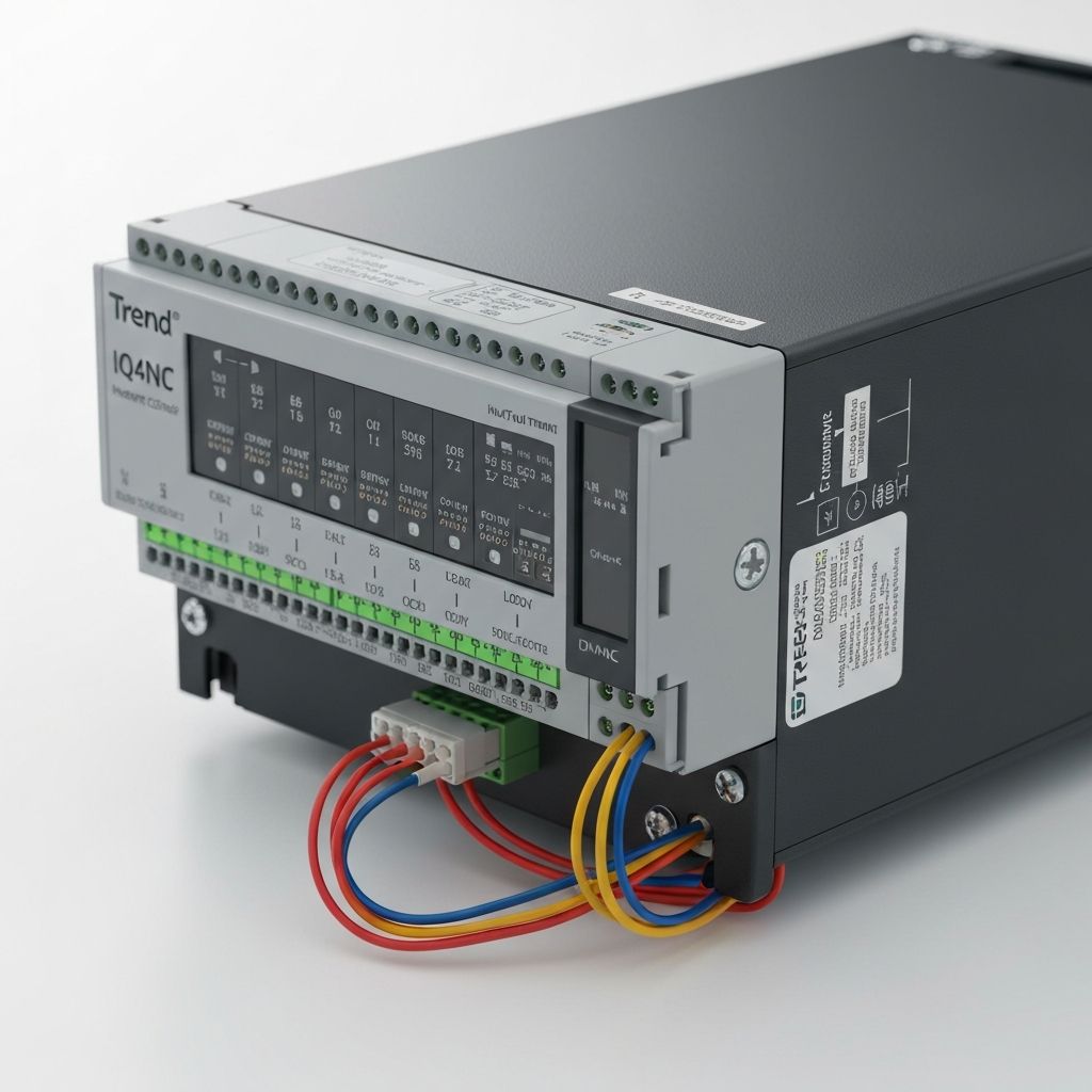
Understanding inputs and outputs is fundamental to working with BMS controllers like the Trend IQ4NC and IQ ECO 412. By correctly identifying and wiring digital and analog I/O, you can build reliable, efficient control systems that monitor and manage building services effectively.
Need help with BMS wiring or controller configuration? Contact Alpha Controls for expert installation and commissioning services.
Our team of building automation specialists is ready to help you optimise your building's performance and efficiency.
Get in Touch